RNC Modules Application Note
Overview
Road Noise Cancellation (RNC) is a feedforward adaptive active noise cancellation (ANC) system for reducing broadband road noise in vehicle cabins. Reference sensors (accelerometers, microphones) capture the noise source; adaptive digital filters synthesize a cancellation signal played through cabin loudspeakers; error microphones inside the cabin measure residual noise and drive online coefficient updates.
The system is fundamentally MIMO: R reference channels feed Y loudspeaker (output) channels, while E error microphone channels close the adaptation loop. Audio Weaver implements this with five cooperating modules from the Advanced module pack:
- StateAllocator — maintains a circular audio history buffer shared across user modules
- CoeffAllocator — holds a coefficient buffer shared across user modules
- FeNLMSUser — implements the Adjoint LMS (filtered-error NLMS) adaptive algorithm
- FxNLMSUser — implements the Multiple-Reference/Multiple-Output FxLMS (filtered-reference NLMS) adaptive algorithm
- FIRUser — multi-channel FIR filter producing the anti-noise control signal
Module Descriptions
StateAllocator
StateAllocator writes incoming audio samples into an internal circular buffer and exposes it to downstream user modules via a 7-word reference frame on its output pin.
| Frame Word | Contents |
|---|---|
[0] |
Buffer offset from the start of the heap |
[1] |
isComplex (1 = complex input, 0 = real) |
[2] |
numChannels |
[3] |
chanLen — useful samples per channel = DELAYSAMPS + inBlockSize + makeEven |
[4] |
heapNum |
[5] |
stateIndex — index of the oldest sample (next write position) |
[6] |
deinterleave flag (1 = deinterleaved, 0 = interleaved) |
The delaySamps argument sets how many past samples per channel are retained beyond the current input block. Deinterleave mode must be enabled (deinterleave = 1) for all adaptive and FIR user modules. In this mode, each channel is stored as a contiguous segment of chanLen samples followed by 2 SIMD padding words; user modules must add +2 per channel when computing inter-channel stride.
CoeffAllocator
CoeffAllocator allocates a floating-point coefficient buffer and exposes it through a 5-word reference frame. Adaptive modules write updated coefficients into this buffer each pump; FIRUser reads it to apply the current filter.
| Frame Word | Contents |
|---|---|
[0] |
Buffer offset from the start of the heap |
[1] |
isComplex |
[2] |
numChannels |
[3] |
channelSamps — samples per channel |
[4] |
heapNum |
Channels are stored non-interleaved (all samples for channel 0 first, then channel 1, etc.). Coefficients must be stored in reverse order for FIR and adaptation operations (index 0 pairs with the oldest state sample). The tunable value[] array can be pre-loaded with initial coefficients through the inspector or at design time.
FeNLMSUser — Adjoint LMS (Filtered-Error NLMS)
FeNLMSUser implements the Adjoint LMS algorithm (E. A. Wan, "Adjoint LMS: an efficient alternative to the filtered-x LMS and multiple error LMS algorithms," ICASSP 1996). Rather than filtering the reference signal forward through the secondary path model — as FxLMS does — the Adjoint LMS filters the error signal through the adjoint (time-reversed) secondary path model. Key characteristics:
- The SISO and MIMO weight-update equations are structurally identical, so there is no extra MIMO overhead in the weight-update step.
- The module always adapts at the block rate — one weight update per block — using only the instantaneous error (latest available in the block).
- No separate filtered-reference state buffer is needed, reducing memory bandwidth compared to FxLMS.
- The reference StateAllocator requires more history than for FxLMS (see Configuration section).
- The error StateAllocator must hold at least
numTapsSec − 1past error samples to support the adjoint filtering step.
FxNLMSUser — Multiple-Reference/Multiple-Output FxLMS
FxNLMSUser implements the Multiple-Reference/Multiple-Output Filtered-reference LMS algorithm (S. M. Kuo and D. R. Morgan, "Active noise control: a tutorial review," Proc. IEEE, 1999, Section V.D). Each reference signal is filtered through the secondary path model to produce filtered-reference signals that drive the LMS weight update. Key characteristics:
- Also adapts at the block rate, but accepts an explicit
blockSizeargument to filter the reference at sample rate. - When
stepSize = 0(frozen), secondary-path filtering still runs every pump so that the internal filtered-reference state remains valid and adaptation can resume cleanly. - The reference StateAllocator requires history proportional to the secondary path length; the error StateAllocator requires only minimal history (
delaySamps = 1at any block size). - Offers three normalization modes (0, 1, 2) for flexible cost/accuracy trade-offs.
FIRUser — Multi-Channel FIR Filter
FIRUser implements a multi-channel FIR filter using state and coefficient buffers provided by StateAllocator and CoeffAllocator. In RNC, it operates in GROUP_MODE (filterMode = 1):
numChanCoeffsmust equal R × Y;numChanStatemust equal R.- For each of Y output channels, the R reference channels are each convolved with their corresponding coefficient channel and the results are summed, producing one output sample per group.
- The GROUP_MODE output is negated, making it a ready-to-use anti-noise signal for direct connection to loudspeaker output.
FIRUser validates its inputs at runtime and reports configuration errors in errorCode. Filtering is muted until all inputs pass validation. After the first successful check, the module enters a locked state and only re-validates if heap numbers or buffer offsets change.
Similarly, the adaptive modules output an invalid frame until all inputs pass validation. These use the same conventions for their errorCode variables. A non-zero errorCode in any of these modules indicates a configuration mismatch that prevents correct operation.
See each module's documentation for additional functional details and error codes (where applicable):
System Interconnection
A typical MIMO RNC system with R reference channels, Y loudspeaker channels, and E error microphone channels connects the modules as follows:
- Reference StateAllocator (SRef): accepts R-channel reference audio. Connected to both the adaptive module's SRef input and FIRUser's S input.
- Error StateAllocator (SErr): accepts E-channel error audio. Connected to the adaptive module's SErr input only.
- Adaptive module (FxNLMSUser or FeNLMSUser): holds the pre-measured secondary path impulse responses (fixed at runtime). Connected to both State and Coeff modules at the input and typically to FIRUser at its output.
- Adaptive CoeffAllocators C1 and C2 (ping-pong pair): hold the adaptive filter coefficients. Both typically connect to the adaptive module; the module alternates writes between them each pump. FIRUser's C input typically connects to the adaptive module's C output, which always forwards the frame of the most recently completed buffer. This order can be optionally reversed (i.e. FIRUser first, followed by the adaptive module). When FIRUser and the adaptive module run on the same clock divider (same instance and thread), only one CoeffAllocator is actually needed. In this case the CoeffAllocator's output is connected to both C1 and C2, resulting in an in-place coefficients update.
- FIRUser: S input from the reference StateAllocator; C input from the adaptive module's C output. The negated GROUP_MODE output drives the loudspeakers.
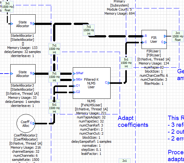
Figure 1: Example system with 3 reference channels, 2 output channels and 2 error channels. This is a single-rate configuration using FxNLMSUser and a single CoeffAllocator.
Multi-Rate Support
Running the adaptation module at a reduced rate can significantly lower the cycle load in some applications. This is at the expense of a slower convergence rate and a higher latency through the adaptation path. In this configuration, the recommended interconnection between RNC modules is via the ChangeThreadV2 module, which helps maintain coherency and synchronization of the various reference frames from StateAllocators and CoeffAllocators. The guideline is the following:
- Keep both StateAllocators in the full-rate thread so that reference state can be accessed by FIRUser with the lowest possible latency.
- Send both StateAllocator frames through the same ChangeThreadV2 so that they remain synced to each other, keeping reference and error state-indices aligned.
- Since ChangeThreadV2 buffers up several frames, and the adaptation module only needs one, the outputs must be downsampled by simply discarding the oldest frames. The most recent frame of each StateAllocator will point to the latest available state that the adaptation module can access.
- Use two distinct CoeffAllocators so that the ping-pong mechanism can prevent race conditions. These should be placed in the same thread as the adaptation module for lower complexity.
- The output of the adaptation module needs to be upsampled before being sent to a second ChangeThreadV2 module, which will buffer down the input for the full-rate thread.
- The second ChangeThreadV2 can then be connected to the C input of FIRUser.
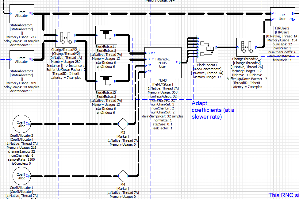
Figure 2: Example system with reduced-rate adaptation (7x clock divider, each thread on a different core). In this configuration, StateAllocator frames are downsampled by extracting the latest frame from each wire, while the adaptation module output is upsampled simply by concatenating copies of the same frame. Two distinct CoeffAllocators are used to avoid race conditions.
See different configurations in the AllocatorUser_*.awd examples found in the \<AWE install folder>\Examples\Module_Usage folder.
ChangeThreadV2 module documentation can be found here: ChangeThreadV2
Configuration Guide
System Parameters
| Symbol | Meaning | Notes |
|---|---|---|
| R | Number of reference channels | numChanRef argument in the adaptive module. |
| Y | Number of output (loudspeaker) channels | numChanOut argument in the adaptive module. |
| E | Number of error microphone channels | numChanErr argument in the adaptive module. |
| P | numTapsAdapt — adaptive filter length (taps) |
Coefficients are stored in reversed order. Channel ordering: output index is the slow index, reference index is the fast index — Y1R1, Y1R2, …, Y1RR, Y2R1, …, YYRR. |
| Q | numTapsSec — secondary path model length (taps) |
Coefficients are stored in reversed order. Note that specifically for the Adjoint method, the secondary path filter is additionally a time-reversed model by design, which in the end results in forward-sequence coefficients (i.e. Fx and Fe secondary coefficient sequences are opposite from each other). Adaptive coefficient sequences are the same in both adaptive modules (also reversed order). Channel ordering: output index is the slow index, error index is the fast index — Y1E1, Y1E2, …, YYEE. Load these channels with the measured secondary path impulse responses before running the system. |
| B | Signal blocksize (samples per pump) | Default blocksize is 1 for module arguments. Reference and error signals must have the same blocksize. FIRUser and FxNLMSUser blockSize arguments must match the input signals (see exception below when setting a different clock divider for adaptation). |
| D | delaySampsRef adaptive module argument |
Delays the reference signal to help align it with the error signal (for adaptation only). The error signal will naturally have a higher latency due to its fed-back path. FeNLMSUser: default delay matches Q, which compensates for the secondary path model delay (see Adjoint LMS) plus 1 sample of feedback latency. FxNLMSUser: default delay is 1, which compensates only for 1 sample of feedback latency. For either module, this delay will typically increase for larger block sizes and/or higher feedback latency. For Filt-X, alignment is typically fully handled by the secondary path filter, but this delay can provide additional flexibility. |
At Blocksize B = 1
FIRUser
| Argument | Value | Notes |
|---|---|---|
numTaps |
P | Must match CoeffAllocator channelSamps |
numChanCoeffs |
R × Y | Must match CoeffAllocator numChannels |
numChanState |
R | Must match reference StateAllocator number of input channels |
blockSize |
1 | Must match reference and error StateAllocators input blocksize |
filterMode |
1 (GROUP_MODE) | Required for MIMO summing and negated output |
Reference StateAllocator (SRef)
Shared by both FIRUser and the adaptive module. delaySamps must satisfy both requirements simultaneously.
| Argument | FeNLMSUser system | FxNLMSUser system |
|---|---|---|
deinterleave |
1 (required) | 1 (required) |
| Input channels | R | R |
delaySamps ≥ (for FIRUser) |
P − 1 | P − 1 |
delaySamps ≥ (for adaptive module) |
P + D − 1 | Q + D − 1 |
| Governing constraint | P + D − 1 (since D ≥ 1) | max(P − 1, Q + D − 1) |
Error StateAllocator (SErr)
| Argument | FeNLMSUser system | FxNLMSUser system |
|---|---|---|
deinterleave |
1 (required) | 1 (required) |
| Input channels | E | E |
delaySamps ≥ |
Q − 1 | 1 (see description) |
FeNLMSUser filters the error through the Q-tap adjoint secondary path model, requiring Q − 1 past error samples. FxNLMSUser needs only the current error sample, so no delay is needed. However, delaySamps has a min value of 1.
CoeffAllocator — Adaptive Filter (C1 and C2, ping-pong pair)
| Argument | Value | Notes |
|---|---|---|
numChannels |
R × Y | One channel per reference–output pair |
channelSamps |
P | Must match FIRUser numTaps and adaptive module numTapsAdapt |
Adjustments for Blocksize B > 1
When the system runs at blocksize B > 1, make the following changes:
| Item | Change |
|---|---|
FxNLMSUser blockSize |
Set to B |
FIRUser blockSize |
Set to B |
Adaptive module delaySampsRef (D) |
Increase by B − 1 (assuming B = 1 before change) |
Reference StateAllocator delaySamps (no change for error StateAllocator) |
Increase by B − 1 (assuming B = 1 before change) |
The delaySampsRef increase of B − 1 is due to the added latency through the error path when increasing the blocksize from B = 1. Changing D requires adjusting the reference StateAllocator delay, while the new blocksize itself is allocated automatically by the StateAllocators (hence no configuration change needed for the error StateAllocator).
FeNLMSUser does not have a
blockSizeargument because — unlike FxNLMSUser — it does not keep reference state internally. ItsdelaySampsRefstill needs the B − 1 increase if the StateAllocators' input-blocksize changes.
Adjustments for Different Clock Divider
If the adaptation module runs at a reduced rate — for example, once every K audio pumps — it must process an effective super-block of K × B samples per invocation:
- Set FxNLMSUser
blockSize = K × B. - Set
delaySampsRef = D_B1 + B − 1(i.e. only increase if blocksize increases from B = 1, otherwise there's no change). - Update StateAllocators'
delaySampsto satisfy the updated requirements. - If
delaySampsRefchanged, thendelaySampson the reference StateAllocator must be adjusted accordingly. - Additionally, running adaptation at a reduced rate means that StateAllocators can overwrite older state before it is accessed by the adaptation module. This requires increasing
delaySampsbeyond its base configuration to compensate for the added read latency. While this extra latency is application-dependent, it is assumed that StateAllocators – which must run at full rate – should not pump more than K times before the adaptation module fully executes. Hence,delaySampsin both StateAllocators should be increased from their full-rate value by K × B samples.
When StateAllocator or CoeffAllocator frames go through different threads on the same instance, configure these with any heap that makes sense for the application. If the frames go through different instances (cores), the shared heap must be used exclusively. Adaptation modules and FIRUser modules don't have these heap restrictions, as their allocated arrays are used only internally.
Ping-Pong Buffer Mechanism
In real-time systems, FIRUser (generating the anti-noise signal) and the adaptive module (updating coefficients) may run in different interrupt service routines or threads. Reading and writing the same CoeffAllocator simultaneously would produce corrupted filter outputs.
The ping-pong mechanism uses two CoeffAllocators (C1 and C2) to eliminate this race condition:
- The adaptive module maintains a
coeffSelectvariable (0 or 1) identifying which buffer is the current write target. - When
coeffSelect = 0: the module reads current coefficients from C1, computes the update, and writes the result to C2. - When
coeffSelect = 1: the module reads from C2 and writes to C1. coeffSelecttoggles at the end of each pump.- FIRUser typically connects to the C frame output of the adaptive module. This output always forwards the frame of the just-written buffer — the one the adaptive module will not write next pump.
The result: FIRUser always reads from a fully-written, stable coefficient set. The adaptive module always writes to the other buffer. No locks or mutexes are needed because the double-buffer structure guarantees temporal separation of read and write access.
It is assumed that FIRUser will run at a rate equal to or higher than that of the adaptive module for this mechanism to be effective.
When FIRUser and the adaptive module run on the same clock divider (same instance and thread), a second CoeffAllocator is not actually needed. However, using two CoeffAllocators allows the source and target memory locations to be distinct, which could yield better performance.
Runtime Controls
Freezing Adaptation
Setting stepSize = 0 freezes the adaptive filter coefficients:
- FeNLMSUser: all adaptation steps are bypassed. Coefficients remain constant and secondary path filtering stops.
- FxNLMSUser: adaptation steps are bypassed, but secondary-path filtering continues running every pump to keep the filtered-reference state current. When
stepSizeis restored to a non-zero value, adaptation resumes from a valid internal state without a transient.
Note that bypassing adaptation also disables the leaky mechanism. If frozen adaptation is desired while still applying the leak factor, a very small non-zero
stepSizevalue must be chosen.
Step Size
The stepSize parameter (μ) controls the adaptation rate:
- Larger μ: faster convergence, higher misadjustment (residual noise floor after convergence), increased risk of instability.
- Smaller μ: slower convergence, lower misadjustment, better stability margin.
When normalization is enabled, the effective per-sample step is μ / ‖x‖² (or μ / ‖x̃‖² for FxNLMSUser mode 2), which compensates for reference signal power variations and gives a more consistent convergence rate across operating conditions. Set stepSize = 0 to freeze; any positive value resumes adaptation.
Leak Factor
The leakFactor parameter introduces weight decay (leaky LMS). The update equation becomes:
w(n+1) = leakFactor · w(n) + μ · e_f(n) · x(n)
leakFactor = 1.0(default): standard LMS/NLMS, no decay.leakFactor < 1.0: weights decay toward zero each iteration. This limits unbounded coefficient growth caused by secondary path modeling errors and reduces noise amplification in low-SNR reference conditions.
Typical values range from 0.9999 (mild leakage) to 0.999 (moderate leakage). Excessive leakage limits achievable cancellation depth.
Normalization Modes
The normalize argument selects the normalization strategy used in the weight update.
FeNLMSUser:
| normalize | Mode | Description |
|---|---|---|
| 0 | LMS | No normalization. Fixed step size μ regardless of reference power. |
| 1 | NLMS | Normalize by reference signal power. More consistent convergence rate across varying reference levels. |
FxNLMSUser:
| normalize | Mode | Description |
|---|---|---|
| 0 | LMS | No normalization. Lowest cost. |
| 1 | NLMS (raw reference) | Normalize by the unfiltered reference power. Lower cost than mode 2; often sufficient in practice. |
| 2 | NLMS (filtered reference) | Normalize by the filtered-reference power. Most accurate; highest cost per pump. |
Coefficient Count and Hardware Alignment
The filter lengths P (numTapsAdapt) and Q (numTapsSec) affect both computation and memory. On targets with SIMD vector processing, the inner loops run most efficiently when the filter length is an exact multiple of the hardware vector width W (typically 4, 8, or 16 floats, depending on the target DSP or CPU):
- When P and Q are exact multiples of W, inner loops can execute entirely with full-width SIMD instructions, yielding maximum throughput.
- Non-aligned lengths produce a scalar tail at the end of each inner loop, reducing SIMD efficiency. Offsets into coefficient vectors can also fall into non-aligned base addresses, preventing some optimizations from running altogether.
- The optimal W is hardware-specific. As a practical guideline, choose P and Q as multiples of 8 or 16 to maximize the chance of hitting the fully-optimized path across a range of targets. Profile on the actual target to verify.
Computational Cost
All costs are in Multiply-Accumulate operations (MACs) per pump. FeNLMSUser has the same cost regardless of blocksize; FxNLMSUser processes B samples per pump through the secondary path filter. Variables: R = numChanRef, Y = numChanOut, E = numChanErr, P = numTapsAdapt, Q = numTapsSec, B = blockSize.
FeNLMSUser (Adjoint LMS) — per pump at any blocksize
| Step | Operation | MACs per pump | Condition |
|---|---|---|---|
| 1 | Filter E error signals through Y × E adjoint secondary path models (Q taps each) | Y × E × Q | Skipped if stepSize = 0 |
| 2 | Compute reference power for normalization | R × P | normalize = 1 only, skipped if stepSize = 0 |
| 3 | Update Y × R × P adaptive weights | Y × R × P | Skipped if stepSize = 0 |
FxNLMSUser (Multiple-Reference/Multiple-Output FxLMS) — per pump at blocksize B
| Step | Operation | MACs per pump | Condition |
|---|---|---|---|
| 1 | Filter R references through Y × E secondary path models (Q taps), over B samples | B × R × Y × E × Q | Always (even when frozen) |
| 2 | — | 0 | normalize = 0, skipped if stepSize = 0 |
| 2 | Compute raw reference power | R × Q | normalize = 1, skipped if stepSize = 0 |
| 2 | Compute filtered-reference power | R × Y × E × P | normalize = 2, skipped if stepSize = 0 |
| 3 | Update Y × R × P adaptive weights + filtered-reference state | R × Y × P × (E + 1) | Skipped if stepSize = 0 |
FIRUser (GROUP_MODE) — per pump
| Operation | MACs per pump |
|---|---|
| Convolve R state channels against R × Y coeff channels (P taps), over B samples | B × R × Y × P |
Algorithm Comparison
FeNLMSUser advantage at large blocksize or many references: Step 1 costs Y × E × Q MACs regardless of R or B — it scales with outputs and errors, not with references or blocksize. FxNLMSUser Step 1 costs B × R × Y × E × Q MACs, growing linearly with both B and R. For systems with many reference channels or large blocksizes, FeNLMSUser can be significantly cheaper in the secondary-path processing step, with the main tradeoff being higher adaptation latency. Memory usage is also typically lower for FeNLMSUser due mostly to the absence of the filtered-reference state array.
FxNLMSUser normalization mode 2 (filtered-reference power) is the most accurate NLMS normalization — it uses the true filtered-reference power that the weight update depends on — but adds R × Y × E × P MACs per pump. Mode 1 (raw reference) adds only R × Q MACs and is sufficient in most practical systems. Mode 0 has no normalization cost.