ALSA IO
Note
This document is currently under active development. Content may be updated, revised, or removed without notice.
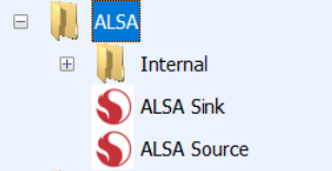
This section describes the modules for streaming audio between the High-Level OS (HLOS) and Audio Weaver. AWE-Q Release 4.4.B introduces new ALSA Source and ALSA Sink modules with integrated sample rate converters. The goal is to simplify usage and prevent configuration errors which plagued earlier releases. The 2 main modules to use are:
These modules look and act like hardware pins, but they are implemented as Audio Weaver modules. As modules, they have all of the functionality of a module (module arguments, parameters, inspectors, thread placement, etc.). You should add one ALSA Source module for each ALSA playback device, and one ALSA Sink module for each ALSA capture device. The ALSA I/O modules can be on any of the audio processing cores including Hexagon DSPs and Arm cores.
The ALSA Sink and Source modules have integrated sample rate converters (SRCs). The SRCs allow Audio Weaver to operate at a fixed sample rate while the HLOS can stream audio at any of these standard audio sample rates: 8000, 11025, 12000, 16000, 22050, 24000, 32000, 44100, 48000, 64000, 88200, 96000, 128000, 176400, 192000, 256000, 352800, 384000.
TinyALSA Integration
Behind the scenes, these modules are implemented as TinyALSA plugins. Data is streamed via shared memory and care was taken to minimize the number of buffer copies. A figure showing the HLOS and Audio Weaver portions of an ALSA Source device are shown below.
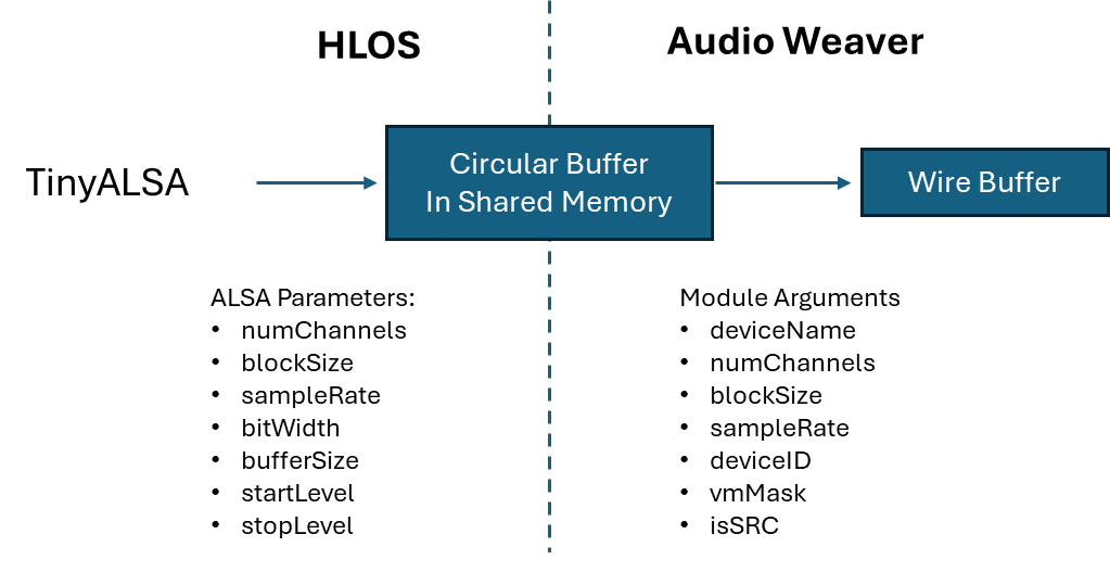
In Audio Weaver, you specify the output wire properties (numChannels, blockSize, sampleRate, and dataType) as module arguments. These are fixed values and do not change at run-time. You also specify the deviceName (up to 31 characters) and a unique integer deviceID. The HLOS application opens the ALSA playback device based on its deviceName or deviceID. When the device is opened by the HLOS, the application sets these properties:
numChannels - number of channels that the HLOS will stream.
blockSize - number of samples that the HLOS will write per transfer.
sampleRate - sample rate of the data.
bitWidth - number of bits per sample (i.e., 8, 16, 24, or 32). All data is fixed-point with a fractional representation.
bufferSize - size of the circular transfer buffer, in samples. We recommend that the bufferSize is at least 4 x blockSize. Larger buffers reduce underruns but increase latency.
startLevel - used during device startup. Number of samples that must be in the circular buffer before Audio Weaver starts reading data.
stopLevel - TBD.
These properties are independent of the Audio Weaver arguments. For example, the HLOS can use a blockSize of 480 samples (10 msec) while Audio Weaver uses a blockSize of 48 samples (1 msec). Other mismatches are handled as follows:
If there is a sampleRate mismatch, then if the module is configured to use the SRC, then there is no error. Otherwise, there will be an error when the device is opened.
bitWidth mismatch. Never happens. The HLOS can stream at any bitWidth and Audio Weaver always converts this to fract32.
numChannels mismatch. Audio Weaver employs its “channel matching” algorithm. For example, suppose that Audio Weaver is configured to output 4 channels. If the HLOS opens the device for 2 channels, then the HLOS data will be on channels 1 and 2 while channels 3 and 4 will be set to zero. If the HLOS opens the device for 6 channels, then channels 1 to 4 will be output on the Audio Weaver pin while channels 5 and 6 will be skipped. Do we do this or do we require that the number of channels match perfectly between the HLOS and Audio Weaver?
Audio data is always streamed as fractional data from the HLOS to Audio Weaver. We do not currently support floating-point WAV files. The processing inside the ALSA modules is all fixed-point and if you request a floating-point output from the ALSA Source module it will insert a TypeConversion module for you automatically.
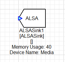
ALSA Source Module
The module appears as follows on the canvas. It appears as a “pin”, but is actually a module.
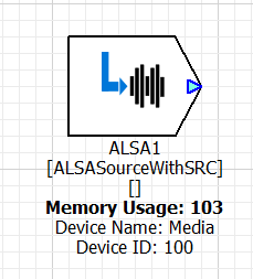
By default, the module has a single output pin which contains the audio from the HLOS. If you set the “outputStreamInfo” argument to true, you will see another pin labeled “SI” on the bottom of the module.
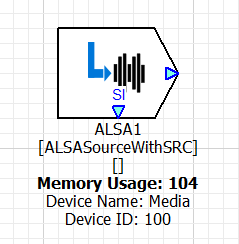
This pin contains stream information which allows you to tell when the state of the ALSA device. It outputs an integer valued control signal on a block-by-block basis and indicates:
0 = Stream is idle. No audio is being streamed.
1 = First block of the stream.
2 = Middle of the stream
3 = Last block of the stream.
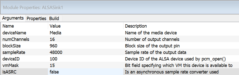
Module Arguments
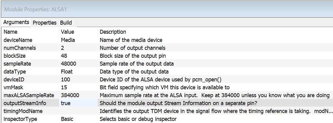
deviceName - string giving a unique identifier to the device. The HLOS can search for devices based on this name. The name is limited to 31 or fewer characters.
{numChannels, blockSize, sampleRate, dataType} - set the output wire properties of the device. As shown above, the device outputs stereo data, every 1 msec, at a sample rate of 48 kHz. The audio data is output as floating-point sample values.
deviceID - integer ID which is exposed to the HLOS. This is the deviceID passed to the pcm_open() command and is used to find the device. Note, each ALSA device needs to have a unique deviceID and this is checked at build time.
vmMask - bit mask which specifies which OS’es the audio device is available in. For example, if you have a “safety chimes” device, it should only be available in the PVM, instead of the GVM. More details are in Section TBD.
maxALSASampleRate - This specifies the highest sample rate that the ALSA device will ever receive from the HLOS. This setting affects internal memory allocation and by default it is set to allocate the worst case (i.e., large buffers). If you know what you are doing and need to save memory, then you can reduce this to a lower sample rate. If this is set incorrectly, you will get distortion at the output of the ALSA module!
outputStreamInfo - Boolean value which causes the Stream Info pin (“SI”) to appear on the module. By default, this is false and SI does not appear.
timingModName - This is a string which names the TDM device which is the primary output path for this ALSA Source module. This information is used to generate time stamps usable by the HLOS to synchronize audio and video.
inspectorType - Allows you to select between the Basic inspector (the default) or a large Debug inspector with more controls.
The circular buffer in shared memory is not allocated by Audio Weaver, but by the TinyALSA plug-in when the audio device is opened by the HLOS. This memory is allocated outside of the Audio Weaver heaps and you will not see this memory in the Audio Weaver profiling.
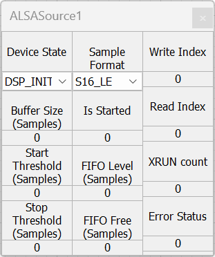
Basic Module Inspector
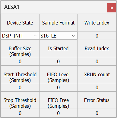
The inspector is used for viewing the state of the module. There are no user settable parameters here.
{Sample Format, Buffer Size, Start Threshold, Stop Threshold} - Parameters set when the playback device is opened by the HLOS.
Device State - Can be one of 3 values:
DSP Init - Audio Weaver has finished initializing the device, but it has not yet been opened by the HLOS. Integer value of 1.
Stopped - The HLOS has opened the device but is not streaming data. Integer value of 2.
Started - The HLOS has opened the device and is streaming data. Integer value of 3.
Is Started - Boolean which indicates whether the HLOS is streaming audio data.
FIFO Level - Number of samples in the circular transfer buffer that can be read by Audio Weaver. If this goes to zero, then an underrun occurs.
FIFO Free - Number of samples that can be written into the transfer buffer by the HLOS. If this goes to zero, then an overrun occurs.
{Write Index, Read Index} - pointer offsets when accessing the circular buffers.
XRUN Count - Number of overruns or underruns that have occurred. The ALSA Source device can only have underruns.
Error Status - Internal API error status. Should be 0 during normal operation.
Full Debug Inspector
If you select the “Full_Debug” inspector on the Module Arguments, then more controls appear that are useful for debugging SRC issues:
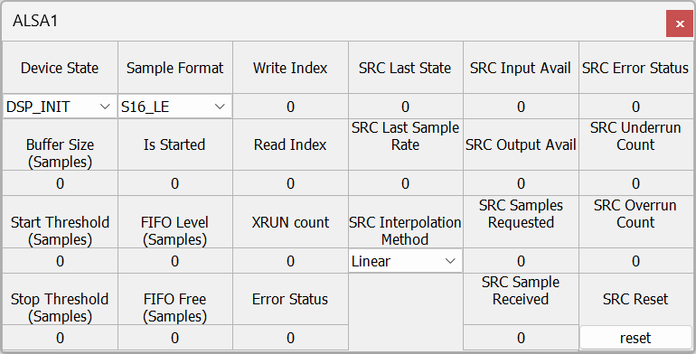
SRC Last State - Read back variable. Indicates whether the device is active, or not.
SRC Last Sample Rate - Read back variable. Sample rate of the data supplied by the ALSA device.
SRC Interpolation Method - User settable parameter. Specifies whether the device implements Linear or Cubic interpolation. Currently, this does nothing and linear interpolation is always used.
SRC Input Avail - Read back variable. Number of samples at the ALSA sample rate that can be written into the SRC’s jitter buffer.
SRC Output Avail - Read back variable. Number of samples at the Audio Weaver sample rate that can be read from the SRC based on the level of the jitter buffer.
SRC Samples Requested - Read back variable. Number of samples requested from the ALSA Source device. These are to be sent during the next pump cycle.
SRC Samples Received - Read back variable. Number of samples that were actually received from the ALSA Source device.
SRC Error Status - Read back variable. Returns API error status. Should be 0 during normal operation. See Section TBD for how to interpret this value.
SRC Underrun Count - Read back variable. Number of underruns when attempting to read data out of the ASRC. If you get underruns, then the HLOS is not writing data fast enough.
SRC Overrun Count - Read back variable. Number of overruns. An overrun indicates that the jitter buffer in the ASRC is full. This should never happen for ALSA Source devices.
SRC Reset - User settable parameter. Click “reset” to set the errorStatus and all counters back to zero.
ALSA Sink Module
This whole section needs to be updated!
This module streams audio from Audio Weaver to the HLOS. It is similar to the ALSA Source Module. It appears as a “pin”, but is actually a module.
Module Arguments
These are shown below but are exactly the same as the ALSA Source module
Module Inspector
The inspector is shown below but is exactly the same as the one for the ALSA Sink module.
ALSA Tips and Tricks
Using Internal Variables
The ALSA modules have internal variables which are useful for controlling audio processing in your signal flow. You can use ParamGet modules to read these variables and put them onto control wires. We list the useful variables:
deviceState - int32_t. This is the “ALSA Device State” variable shown on the inspector. Possible values are: 1 = The DSP has initialized the device but it has not yet been opened by the HLOS. 2 = The HLOS has opened the device but it has not been started. 3 = The device is started and data is streaming.
isStreaming - int32_t. The is the “Is Started” variable on the inspector. This indicates if the device has been started via the inspector.
ALSA Troubleshooting
This section describes how to properly configure the ALSA devices to prevent audio dropouts. If you get dropouts, then this is because the client HLOS applications are not writing or reading data fast enough. Different techniques are needed for ALSA Source and ALSA Sink modules.
ALSA Source Underruns
Suppose that the HLOS opens the device with a 5 msec block size and a buffer size of 10 msec, and that Audio Weaver is configured to read data every 1 msec (The discussion here is based on block times which are easier to follow. The actual configuration is based on block sizes.) (We are ignoring asynchronous devices here, but the same explanation holds.) The ALSA Source module will output zeros after the device has been opened and the HLOS has not yet written data. This does not count as an underrun. The HLOS writes the first 5 msec block of data. The ALSA Source module sees the new data and then starts streaming data. It reads data out of the circular transfer buffer 1 msec at a time. The HLOS needs to write the next block of data within 5 msec or an underflow will occur.
Sometimes the HLOS needs more time to write data. This is where the startLevel of the ALSA device comes into play. Suppose that the HLOS application opens the ALSA device with a buffer size of 40 msec and a startThreshold of 20 msec. The HLOS application then writes 4 blocks of data. The circular transfer buffer now holds 20 msec of data and the startLevel has been crossed. At this point, the ALSA Source module stops writing zeros and starts streaming data. Since there is 20 msec of data (the startLevel) in the buffer, the HLOS has more time to refill and write the next block.
Of course, the startLevel increases the latency, but often this is needed to eliminate underruns. These are recommended minimum settings for ALSA Source devices used with Linux and Android operating systems:
blockSize 10 msec
bufferSize 40 msec (4 x blockSize)
startThreshold 20 msec (2 blockSize)
stopThreshold TBD msec
QNX is more deterministic, which allows you to reduce the block size and reduce latency:
blockSize 5 msec
bufferSize 20 msec (4 x blockSize)
startThreshold 10 msec (2 blockSize)
stopThreshold TBD msec
ALSA Sink Overruns
In a similar fashion, it is possible to get overruns if the HLOS does not read data quickly enough from the ALSA Sink device. To solve this problem, you have to increase the ALSA buffer size, and thereby increase the size of the circular transfer buffer. Adjusting the startThreshold and stopThreshold does not help.
Sample Rate Conversion Overhead
The ALSA Source and Sink SRC modules only do sample rate conversion if there is a mismatch between the ALSA sample rate and the Audio Weaver sample rate. In Release R4.0, the cost of 44.1 to 48 kHz sample rate conversion is about 30 MHz per channel. The cost increases linearly with the output sample rate. For example, converting 44.1 to 96 kHz costs about 60 MHz per channel.
vmMask
This is a module argument to the ALSA Source and Sink devices. It is a bit mask, and allows you to restrict which operating systems have access to specific ALSA source and sink devices. For example, you may have an ALSA device dedicated to safety chimes, and only want applications running on the PVM to stream data to this device.
The vmMask bitfield maps to specific operating system as follows TBD.
ALSA Error Status Values
Section TBD.
ALSA Source Sample Rate Conversion Module (Used Internally)
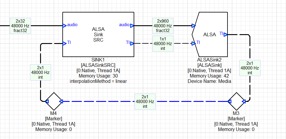
If you need Audio Weaver to do sample rate conversion of ALSA streams, set the “isSRC” module argument to true. This will add two more pins to the ALSA Source module which are used to exchange timing information. These pins are used in conjunction with the ALSA Source Sample Rate Converter module as shown below:
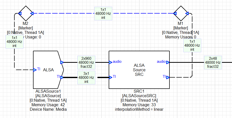
In this example, the ALSA Source SRC module is configured to output a block size of 48 samples at 48 kHz. The ALSA Source SRC module contains the DSP Concepts’ ASRC library which was described in Section TBD. The ALSA Source SRC module “pulls” data from the ALSA device and writes it into the ASRC’s jitter buffer. It pulls enough data to generate 48 samples during the next pump cycle. The ALSA Source SRC module communicates how many samples are required during the next pump cycle by the integer value in its TI output pin. For example, if the sample rate of the ALSA stream is 44.1 kHz, then the ALSA Source SRC would request 44 or 45 samples in order to generate 48 output samples at 48 kHz.
The ALSA Source module shown above has an output block size of 960 samples. 960 samples are not transferred every time, only as many samples requested by the ALSA Source SRC (This is how varying sample rates are handled in Audio Weaver. The buffers are oversized for the worst case transfer size and side information - in the timing information pins - is used to regulate the flow).
You should configure this to be large enough to support any data request by the ALSA Source SRC. Suppose that the HLOS needs to stream data at 384 kHz. 1 msec of data now equals 384 samples and the wire size should be oversized to allow the ALSA Source SRC to prefill data. We recommend sizing the output block size of the ALSASource module at 2 times the largest block size that is expected. In this case, you set it at 768 samples. This sizing must take into account the output block size of the ALSA Source SRC module. Suppose it is outputting 10 msec of data instead of 1 msec, then the input buffer should be sized at 7680 samples. There is no harm (except in wasted memory) in oversizing ALSA Source module’s output wire.
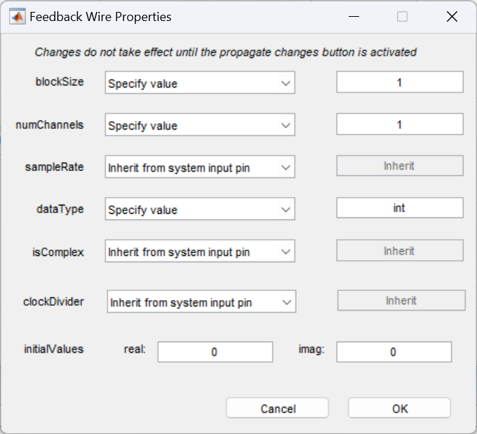
The wire that connects the output of the ALSA Source SRC’s TI pin with the TI input of the ALSA Source module is a feedback wire. You’ll see that this wire is drawn in blue in the figure above. You need to manually configure this wire in Audio Weaver. Right click on the wire, and select “Edit Feedback Properties”. Configure the wire as shown below:
The Timing Information wire between the ALSA Source module and the ALSA Source SRC module contains 3 integer values. You typically don’t have to look at these, but the curious person may want to know:
Wire[0] - isStarted. Boolean
Wire[1] - ALSA sample rate.
Wire[2] - Number of samples written to the output wire. This is usually the number of samples requested by the ALSA Source SRC, but can be smaller if there is insufficient data in the ALSA device’s circular buffer.
If the ALSA device has not started streaming, then all 3 values will be zero.
ALSA Source SRC Module Arguments
The module arguments configure the output wire properties in Audio Weaver.
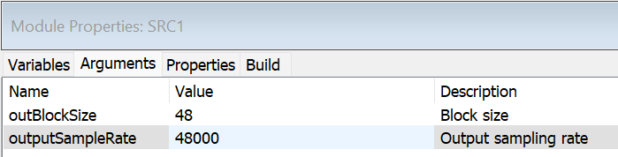
The number of channels is not specified but is instead inherited from the ALSA Source module.
ALSA Source SRC Inspector
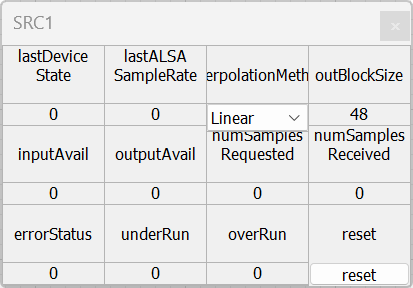
lastDeviceState - Read back variable. Indicates whether the device is active, or not.
lastALSASampleRate - Read back variable. Sample rate of the data supplied by the ALSA device.
InterpolationMethod - User settable parameter. Specifies whether the device implements Linear or Cubic interpolation. Currently, this does nothing and only linear interpolation is used.
outBlockSize - Read back variable. Output block size of the Audio Weaver. This should equal the constructor argument outBlockSize.
inputAvail - Read back variable. Number of samples at the ALSA sample rate that can be written into the ASRC’s jitter buffer.
outputAvail - Read back variable. Number of samples at the Audio Weaver sample rate that can be read from the ASRC based on the level of the jitter buffer.
numSamplesRequested - Read back variable. Number of samples requested from the ALSA Source device. These are to be sent during the next pump cycle.
numSamplesReceived - Read back variable. Number of samples that were actually received from the ALSA Source device.
errorStatus - Read back variable. Returns API error status. Should be 0 during normal operation. See Section TBD for how to interpret this value.
underRun - Read back variable. Number of underruns when attempting to read data out of the ASRC. If you get underruns, then the HLOS is not writing data fast enough.
overRun - Read back variable. Number of overruns. An overrun indicates that the jitter buffer in the ASRC is full. This should never happen for ALSA Source devices.
reset - User settable parameter. Click “reset” to set the errorStatus and all counters back to zero.
ALSA Sink Sample Rate Conversion Module (Used Internally)
If you need Audio Weaver to do sample rate conversion of ALSA streams, set the “isSRC” module argument to true. This will add two more pins to the ALSA Sink module which are used to exchange timing information. These pins are used in conjunction with the ALSA Sink Sample Rate Converter module as shown below:
In this configuration, the feedback wire from the ALSA Sink module to the ALSA Sink SRC now contains 2 elements:
Wire[0] - isStarted. Boolean
Wire[1] - ALSA sample rate.
If the ALSA device has not started streaming, then both values will be zero.
ALSA Sink SRC Module Arguments
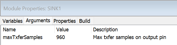
This argument specifies the block size at the output of the ALSA Sink SRC module and should be sized based on the highest sample rate that the ALSA Sink module will output.
ALSA Sink SRC Inspector
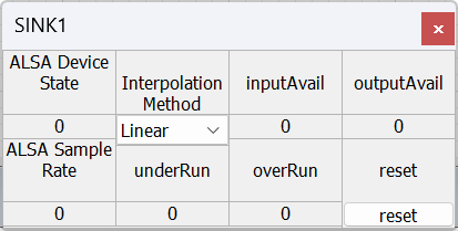
ALSA Device State - Read back variable. Indicates whether the device is active, or not.
ALSA Sample Rate - Read back variable. This is the sample rate of the ALSA stream and configures the output sample rate of the ASRC algorithm. This information is communicated via the 2 element timing information (TI) pin.
InterpolationMethod - User settable parameter. Specifies whether the device implements Linear or Cubic interpolation. Currently, this does nothing and only linear interpolation is used.
inputAvail - Read back variable. Number of samples at the ALSA sample rate that can be written into the ASRC’s jitter buffer.
outputAvail - Read back variable. Number of samples at the Audio Weaver sample rate that can be read from the ASRC based on the level of the jitter buffer.
underRun - Read back variable. Number of underruns when attempting to read data out of the ASRC. If you get underruns, then the HLOS is not writing data fast enough.
overRun - Read back variable. Number of overruns. An overrun indicates that the jitter buffer in the ASRC is full. This should never happen for ALSA Source devices.
reset - User settable parameter. Click “reset” to set the errorStatus and all counters back to zero.