Snapdragon Specific Modules
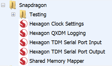
Audio Weaver includes a set of Snapdragon specific audio modules. These modules provide additional control and capabilities. These modules are found in Audio Weaver in the “Snapdragon” folder of the Module Browser.
We also describe how the Audio Weaver Event module operates in the context of a Snapdragon system. Each module is described in turn.
QXDM Logging
This module works in conjunction with the Qualcomm diagnostics and logging APIs. It allows you to stream real-time data from the Audio Weaver signal flow to the Qualcomm QXDM logging APIs. Once the data has been captured by QXDM, it can be parsed by the Qualcomm “QCAT” tool to generate WAV files.
The module has a single input pin and accepts fract32 data. It supports any number of channels and any block size. The module works on any Hexagon DSP and you can have multiple instances of the module throughout your design.
Module Arguments:
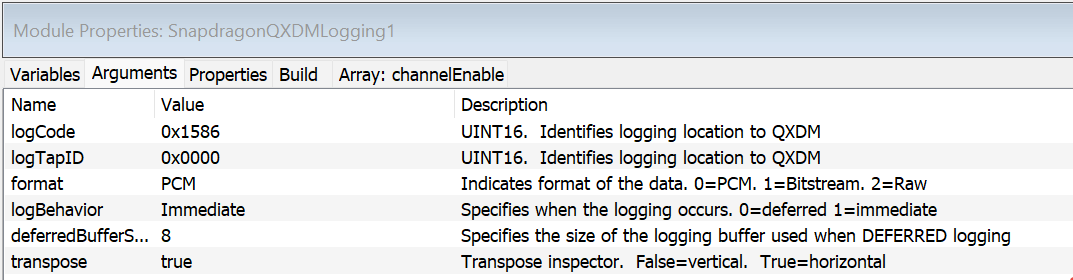
logCode. This is a UINT16 that is entered as a hexadecimal string (e.g., 0x1586). It is used together with logTapID to uniquely identify this module. There are a fixed number of logCode’s available and you select from a droplist:
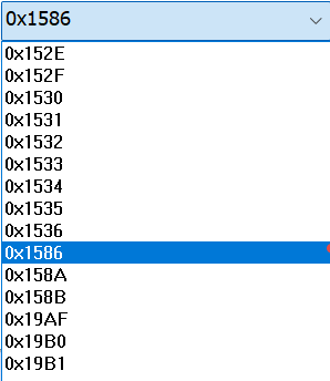
If you are logging PCM data, then it doesn’t matter which logCode you use; it only matters that you pick the matching one in the QXDM application.
logTapID. This is a UINT16 that is entered as a hexadecimal string (e.g., 0x1234). It is used together with logCode to uniquely identify this module.
format. An integer which specifies the format of the data. Allowable values are: 0=PCM (the default), 1=Bitstream, and 2=Raw. The format flag is used by the Qualcomm tools to interpret the data. In Audio Weaver, you should stay with PCM (the default).
logBehavior. An integer which specifies in which thread the logging occurs. 0=deferred. 1=immediate (the default). If immediate, then the QXDM calls happen from the module’s real-time thread. If deferred, then several blocks are buffered up and then the calls to QXDM happen from a non-real-time thread.
deferredBufferSize. An integer which specifies the size of the circular buffer used for deferred logging. This specifies the number of blocks of data to store in the circular buffer.
transpose. Specifies if the inspector is drawn horizontally (the default) or vertically
logCode and logTapID are used to generate the file names by the QCAT utility.
The module can operate in “Immediate” mode which causes the QXDM functions to be called directly from the module’s real-time thread. Data is logged one block at a time. In “Deferred” mode, the data is added to a circular buffer. When the circular buffer is half full, then the module’s Set() function is called using Audio Weaver’s deferred functionality. The Set() function repeatedly calls the QXDM function to log the data. Note that if the number of blocks in the deferred buffer is large, then you may overwhelm the QXDM subsystem. We recommend keeping the deferredBufferSize between 6 and 12 blocks.
Inspector
The module’s inspector is shown below when there are 6 channels being logged. This is the default horizontal orientation.
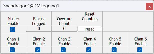
The controls are as follows:
Master Enable - A single Boolean which enables or disables the logging. By default, this is TRUE.
Chan N Enable - This is an array of Boolean values, one per channel. This allows you to log a subset of the channels. By default, channelEnable is all ones and all channels will be logged.
Blocks Logged - this is a counter which increments every time a block of data is logged.
Overrun Count - This increments anytime that Audio Weaver is unable to log a block of data. This may be because the QXDM API returns an error, or the buffer of deferred data is full.
Reset Counts - This is a momentary switch which resets Blocks Logged and Overrun Count.
Example
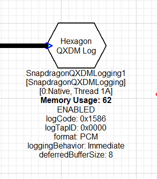
This example streams 2 channels of audio data to QXDM. The first channel is a sine wave and the second is pink noise.
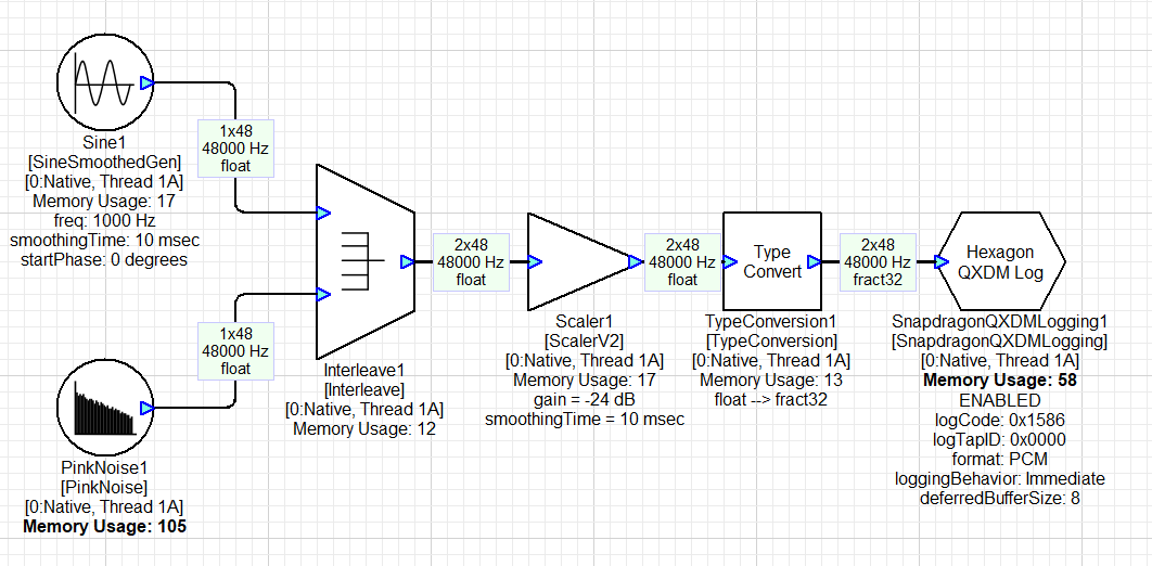
The QXDM module has the default settings and streams to logCode 0x1586 and logTapID 0x0000.
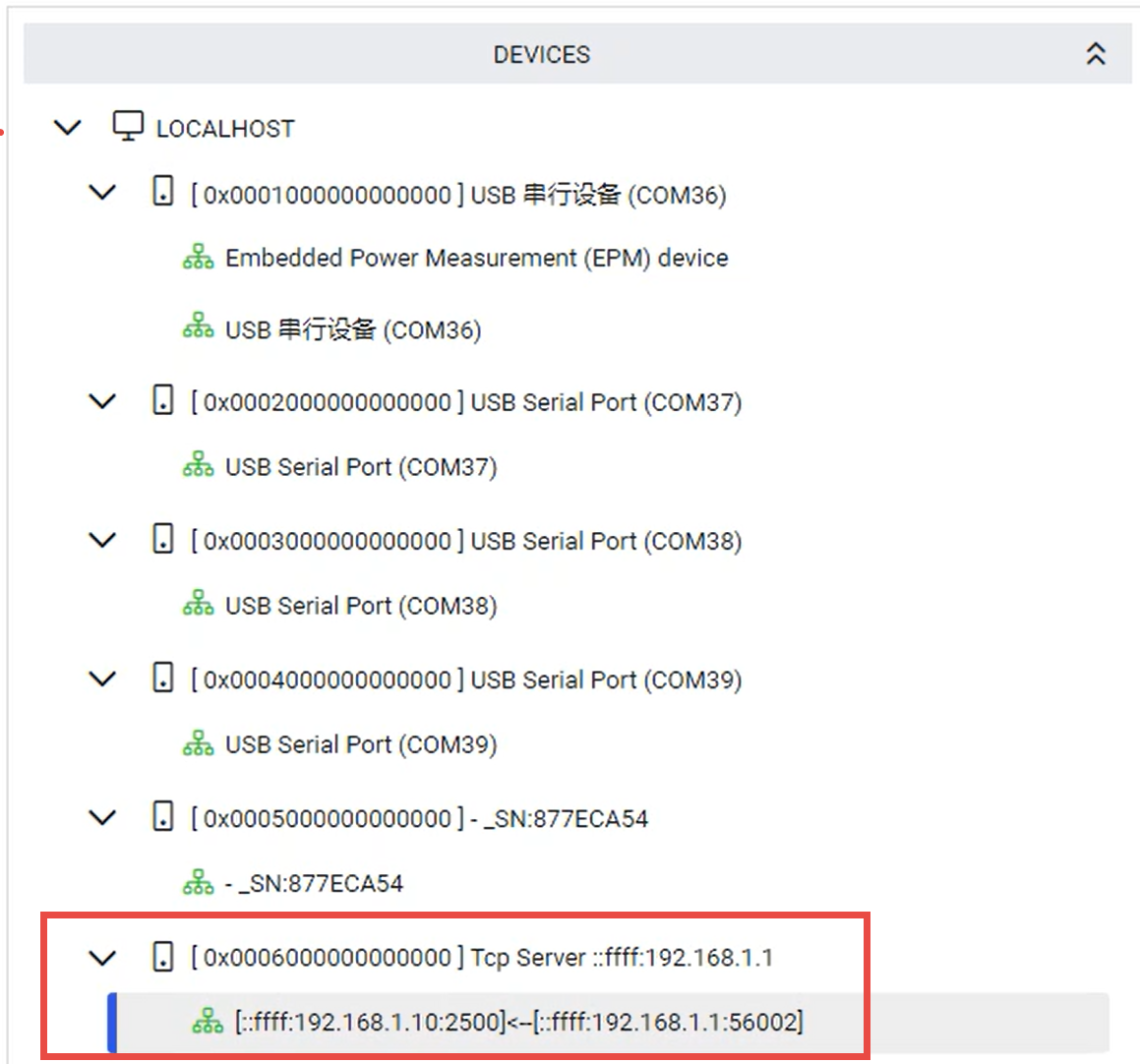
Next, start the Qualcomm “QUTS Status App” and connect to your target device
Then launch QXDM. Go to the Tools menu and select “CFG File Generator”. On the right side of the dialog, search for the logID that you selected. If you do not select this, then the QXDM module will not log packets and you will get overruns.
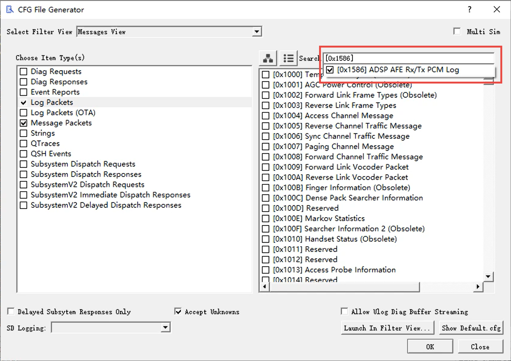
Click “OK” to dismiss the window. At this point, data will be logged by QXDM. Build and run the system in Designer. The inspector will display the number of Blocks Logged:
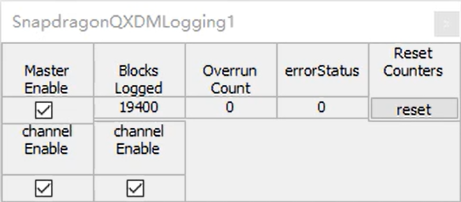
The number of blocks logged should match the pump rate of your module. In this case, it updates 1000 times per second.
Return to QXDM to export your data. Right click and select “Copy All Items to File…” This saves an HDF file to disk.
Next, using the QCAT utility to convert the HDF file to WAV data. Start by opening the HDF file (File→Open).
Then on the View menu select “Vocoder Playback”. Select “Replace Dropped Frames”. This option will use the time stamps of the data packets to reconstruct the WAV data. If there are missing frames (because of dropped QXDM packets, or because you disabled recording or certain channels) then zeros will be inserted.
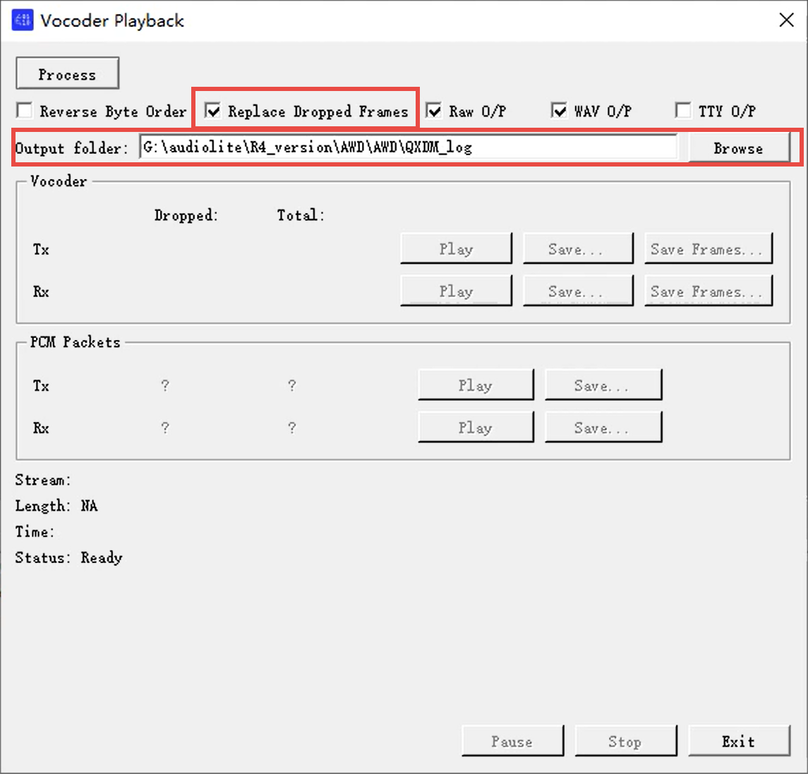
Click “Process” in the upper left corner to generate the WAV files. The QCAT utility generates 3 files per recorded channel: labels, raw data, and WAV data. In this example, it generates the files:
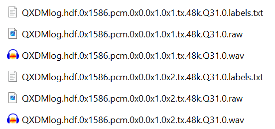
Interpreting the last row:
0x1586 = logCode
0x0 = session ID
0x1 = tapID
0x2 = channel number
Tx = direction. All from modem perspective. Tx = upstream. Rx = to loudspeaker
48 kHz = sample rate
Q31 = numeric format
0 = ???
The file names have the logCode, logTapID, and channel name embedded. Opening the WAV files in Audacity, we see:
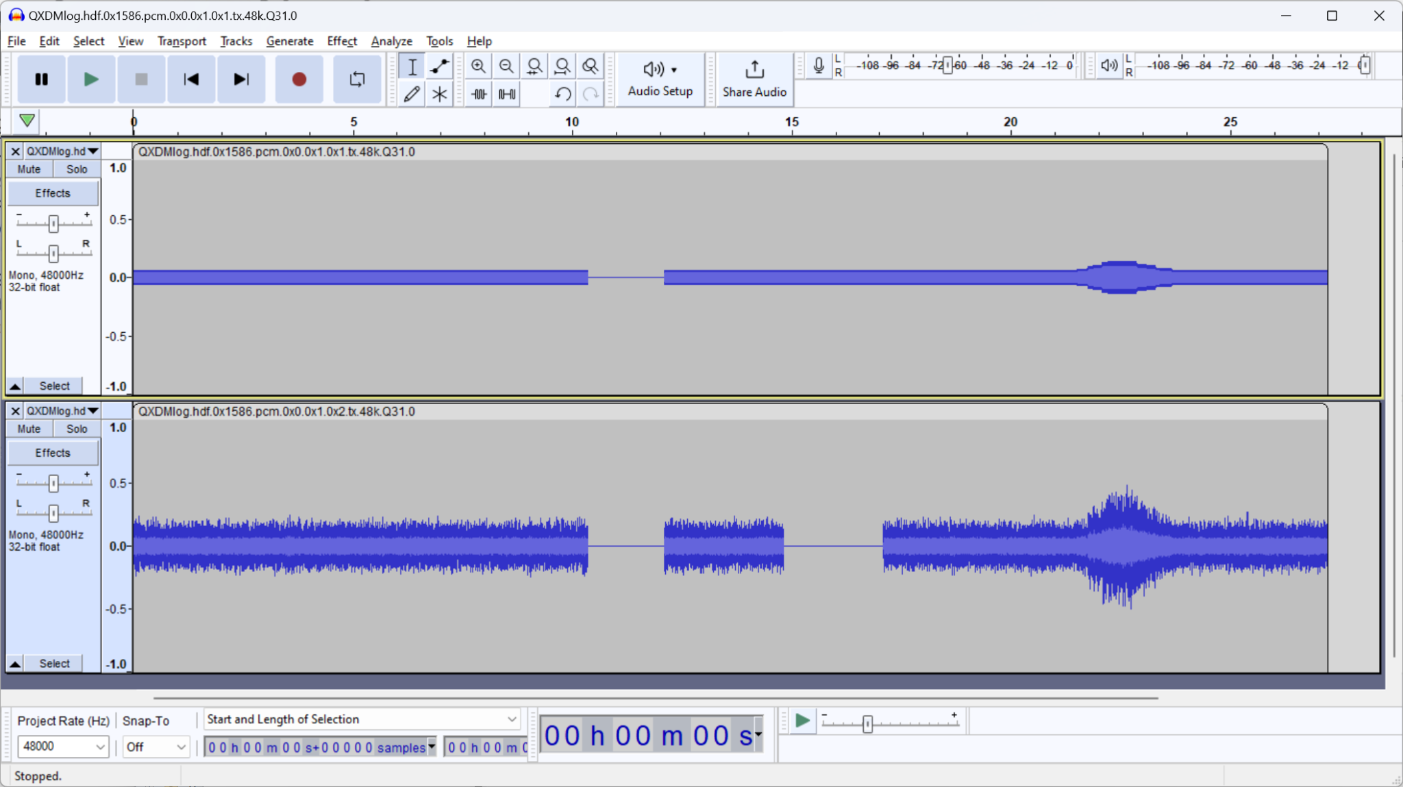
The gap around 11 second was because the “masterEnable” inspector button was toggled. The gap in channel 2 at 15 seconds was because the channelEnable” was toggled. If you do not select “Replace Dropped Frames” in QCAT, then the files will be shorter (no zero periods) and discontinuous.
Troubleshooting
Overruns are occurring
Did you remember to enable your logID in QXDM?
You may be overwhelming the QXDM subsystem and need to reduce the amount of data being logged. Reduce the number of channels or the sample rate of the data collected.
The WAV data is discontinuous
It is possible that no overruns are reported and yet the collected WAV data is discontinuous. When data is passed from Audio Weaver to QXDM, there is an indication that the data was successfully received by QXDM (if not, then Overrun Count increments). There is a second step where QXDM sends the data to the PC. If this fails, there is no indication back to Audio Weaver. Audio Weaver delivered the data to QXDM but QXDM had trouble logging it to the PC. As above, you’ll need to reduce the data rate.
Clock Settings
This module is part of R4.0 and will be replaced by the Clock Voting module in R4.1
This module allows you to change the Hexagon DSP’s clock speed and the speed of its DDR memory access. The module has no input or output pins, and can be placed in any Hexagon thread. The module does not do audio processing per se, but its Set function sets the internal Hexagon state. The module can be placed into any Hexagon thread (it doesn’t matter what thread it runs in).
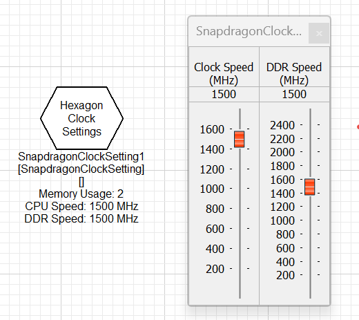
When the Hexagon DSP first boots, it uses the clock speed settings from the awe_config.xml file. Next, when the Audio Weaver signal flow is loaded (the AWB), if it contains a Clock Settings module, then this module will override the initial settings. Finally, this module can be used to adjust the Hexagon clock during run-time. Adjustments can be made using the inspector or with a ParamSet module.
If your design needs a fixed clock speed, then just update the awe_config.xml file. Only use this module if you need to dynamically adjust the clock speed.
Clock Voting
This module allows you to change the Hexagon DSP’s clock speed and the speed of its DDR memory access. The module has no input or output pins, and can be placed in any Hexagon thread. The module does not do audio processing per se, but its Set function sets the internal Hexagon state. The module’s Get function reads back the actual clock settings. This allows you to verify the actual clock settings without using SysMon. The module can be placed into any Hexagon thread (it doesn’t matter what thread it runs in).
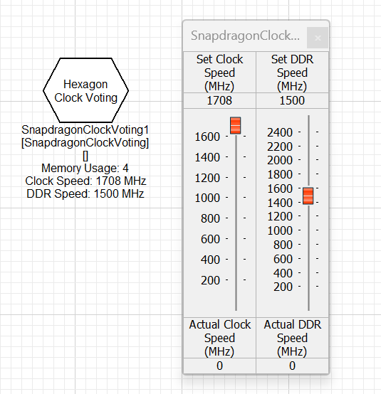
When the Hexagon DSP first boots, it uses the clock speed settings from the awe_config.xml file. Next, when the Audio Weaver signal flow is loaded (the AWB), if it contains a Clock Settings module, then this module will override the initial settings. Finally, this module can be used to adjust the Hexagon clock during run-time. Adjustments can be made using the inspector or with a ParamSet module.
If your design needs a fixed clock speed, then just update the awe_config.xml file. Only use this module if you need to dynamically adjust the clock speed.
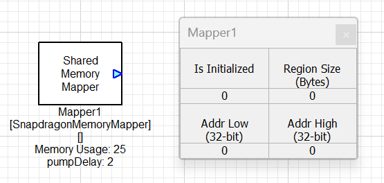
Shared Memory Mapper
This module is used to map shared memory between a client application running in the HLOS and an audio module running in the Audio Weaver signal flow. This module is not used by any of the supplied Audio Weaver modules, but is provided to allow customers to develop their own custom modules that leverage shared memory. The module appears in Designer as shown below.
The module has a single module argument which allows you to set the sample rate of the module’s output wire.
The module has an internal 3 element array “regionInfo” which is used to exchange memory region information between the HLOS and the audio processing cores. This array is initially all zeros when the system is built. During operation, the client application requests memory from the Qualcomm Audio Service (QAS). The application specifies:
-
Size in bytes of the allocation
-
Name of the Shared Memory Mapper module in their signal flow to share the memory with
The QAS performs the following operations:
-
The QAS allocates the memory with the correct sharing attributes
-
The 64-bit physical address and size of the region is written to the module’s regionInfo array via TinyMix commands. This is a 3 element array consisting of 32-bit values:
regionInfo[0] → Low 32-bits of the 64-bit physical address
regionInfo[1] → High 32-bits of the 64-bit physical address
regionInfo[2] → Size of the memory region, in bytes
-
The module’s set function converts the physical address to a virtual address usable by the audio processing core (Hexagon or Arm).
-
The module then outputs the following 3 values on its output wire:
Wire[0] = Low 32-bits of the virtual address
Wire[1] = High 32-bits of the virtual address
Wire[2] = size of the shared region, in bytes
-
The Set function waits pumpDelay pump cycles before returning to the QAS.
-
The QAS then returns the SMMU mapped address to the client and also a handle for deallocating the region later.
After regionInfo is written and successfully converted, the inspector will update:
-
“Is Initialized” becomes 1
-
Addr Low shows the low 32-bits of the virtual address
-
Addr High shows the high 32-bits of the virtual address (On the Hexagon the high 32-bits will always be zero)
-
Region Size - size of the shared memory region, in bytes.
We expect that custom modules will use this information to read and write the shared memory. If the size of the region is zero, then this indicates that the memory has not been allocated, or that it has subsequently been deallocated.
When the client application is finished with the shared memory, it should stop accessing the memory and call the TBD QAS deallocation function. This function:
-
Writes zeros to the named Shared Memory Mapper module’s regionInfo array.
-
The module’s Set function sets the output wire information to 0 and then waits pumpDelay pump cycles.
-
Next it unmaps the memory region
-
Then returns to the QAS, and the QAS returns to the client application.
The pump delay is provided to allow any downstream modules to have sufficient time to stop accessing the memory region.
-
TDM Master
-
Synchronous TDM ports [Paul]
- ASRC coming
- Point to QCM documents
- TDM port limitations
-
ALSA Sink and Source [Paul]
- SRC
-
QXDM Logging [Justin]
-
Event Module [Will]
-
Shared Memory Mapper [Will]
-
Clock Voting [TBD]
-
Future modules
- eAVB, USB, etc.