End-to-End Example
Notice: Pre-Release Documentation
This document is part of a prerelease and is currently a work in progress. Some content may be incomplete, subject to change, or marked as TBD. We are actively updating this documentation and will continue to provide the most accurate and up-to-date information as development progresses. Thank you for your understanding!
This section walks through AWE-Q signal flow best practices using a complete automotive example. It shows how to plan a signal flow across multiple processing cores, understand the latency of the system, control parameters at run-time, and start up the audio system. The design principles are embodied in the SnapdragonGen5_Reference.awd signal flow, which is used throughout to highlight how to implement features in Audio Weaver.
Overview
AWE-Q is the automotive audio platform based on Audio Weaver and targeted at Snapdragon SOCs. Automotive audio has many use cases, and the Audio Weaver signal flow needs to be properly designed to be deployable and easy to maintain. Several core design decisions need to be made which take into account the Snapdragon software architecture and Audio Weaver best practices. These need to be considered at the start of the project to minimize rework later on. The main areas to consider are:
- Which processors boot early and which boot late
- Early audio feature requirements
- 10 MB limitation on boot files for early audio. This includes
- Signal flow data
- WAV playback data
- The flash file system
- How to implement late chimes that require more WAV data
- Progressive loading of the signal flow
- Low latency support for RNC
- TDM port usage
- Which TDM port will be the Synchronous master?
- How to minimize I/O for RNC processing
- Control architecture
- Chimes control during early audio
- Full control during late audio
- How Subcanvases can be leveraged for encapsulating and loading features
- Late loading custom modules via DLLs
- Factory flashing and customization of vehicle audio
- Supporting OTAs and downloadable audio features
The design principles are embodied in the SnapdragonGen5_Reference.awd signal flow. We will use this system throughout to highlight how to implement features in Audio Weaver.
This document focuses on the Qualcomm Gen 5 Snapdragon (SA8797, SA8793, etc.) but most of the principles apply to the Gen 4 SOCs. The main difference to consider is the differences between early and late boot processors:
| Gen 4 | Gen 5 | |
|---|---|---|
| Early boot processors | ADSP, GPDSP0, GPDSP1 | DSP0 |
| Late boot processors | Arm | DSP1, DSP2, Arm |
Signal Flow Planning
The signal flow designer must distribute features across the different processing cores. There are several items which must be considered upfront:
- What features are needed for early audio?
- What is the signal path for latency sensitive features like RNC and ICC?
All other features, like playback processing and telephony, are less sensitive to startup time and I/O latency and can be dealt with later.
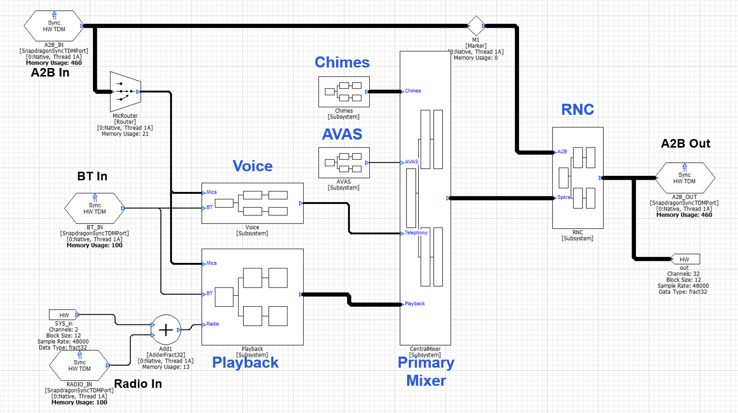
An example top-level signal flow is shown below and we will highlight design decisions in the discussion below.
Early Audio
In the Gen 5 platform, DSP0 is designated for early audio and boots first. All early audio features must exist on this core. The early audio features must be developed using the standard modules which ship in the AWE-Q BSP. This is because custom modules cannot be loaded until the Arm has booted. Early audio also has access to 10 MB of data in total which is used to store the signal flow and WAV files used for chimes players. Given these restrictions, we recommend that you keep early audio features to the minimum required to support regulatory requirements like chimes.
Another requirement is that the Synchronous Master TDM port must be on DSP0 and part of early audio. All other TDM devices are allocated later and look to the SM port to synchronize their clocking. Given these restrictions, the processing is partitioned as follows between the cores:
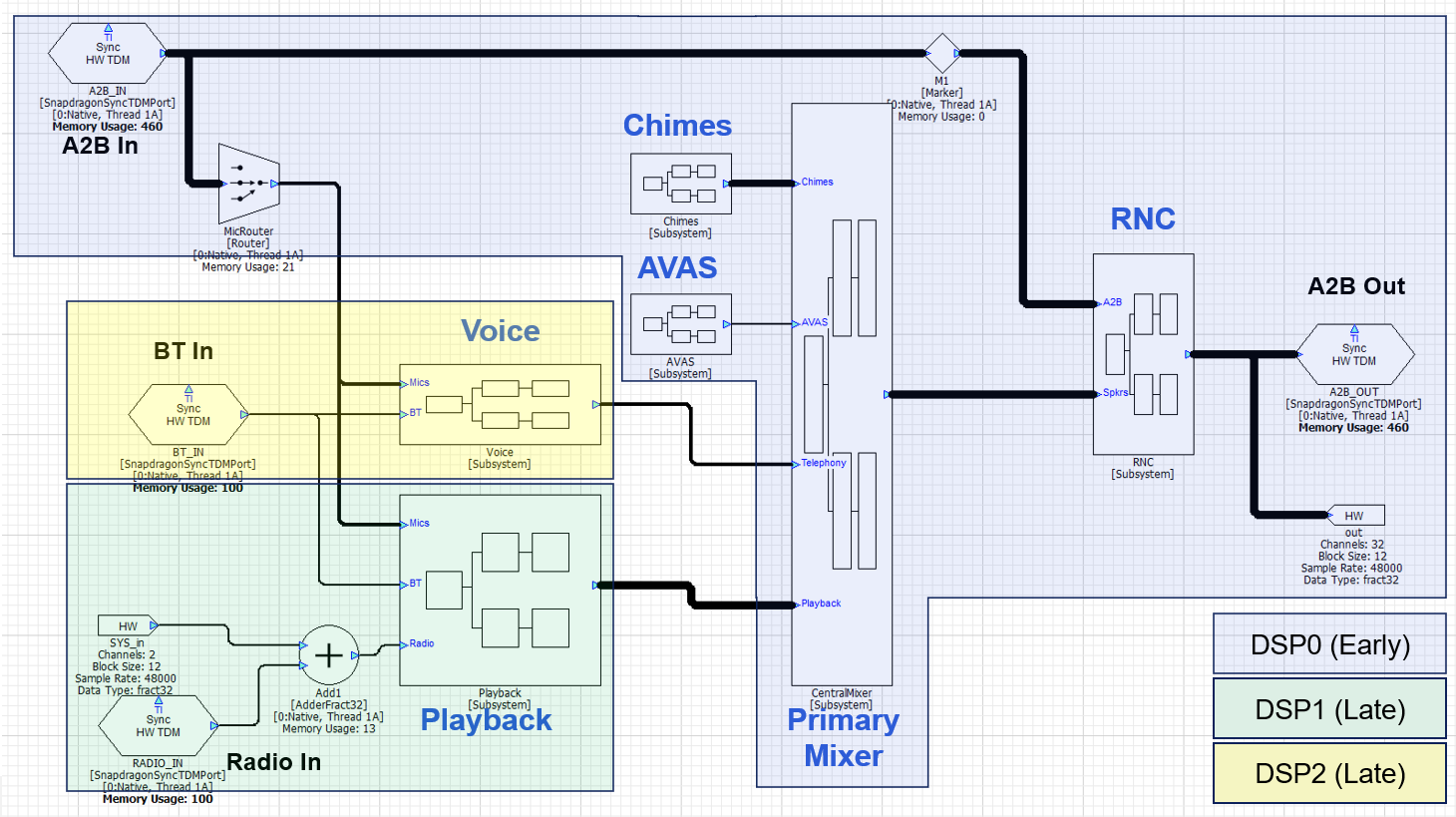
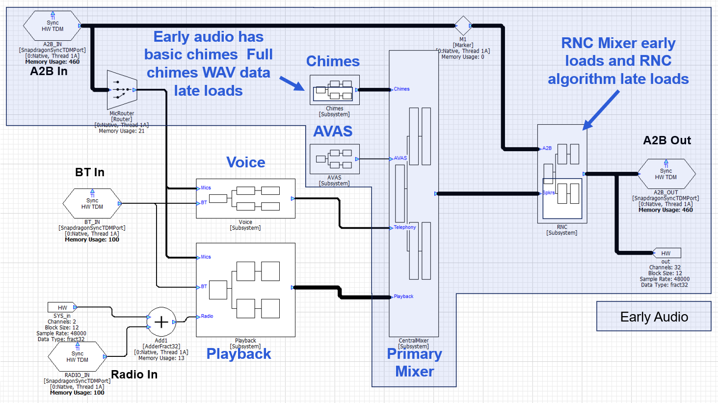
The RNC algorithm will most likely be custom IP and not included in the module set available during early audio. This needs to be late loaded and would be accomplished using a Subcanvas inside of the RNC subsystem. The chimes processing will be segregated into "Early Chimes" with WAV files in the 10 MB flash partition and "Late Chimes" which have access to more data from the HLOS. The data for Late Chimes will be loaded via a Shared Memory Mapper module. The early audio processing with these 2 carve outs is shown below.
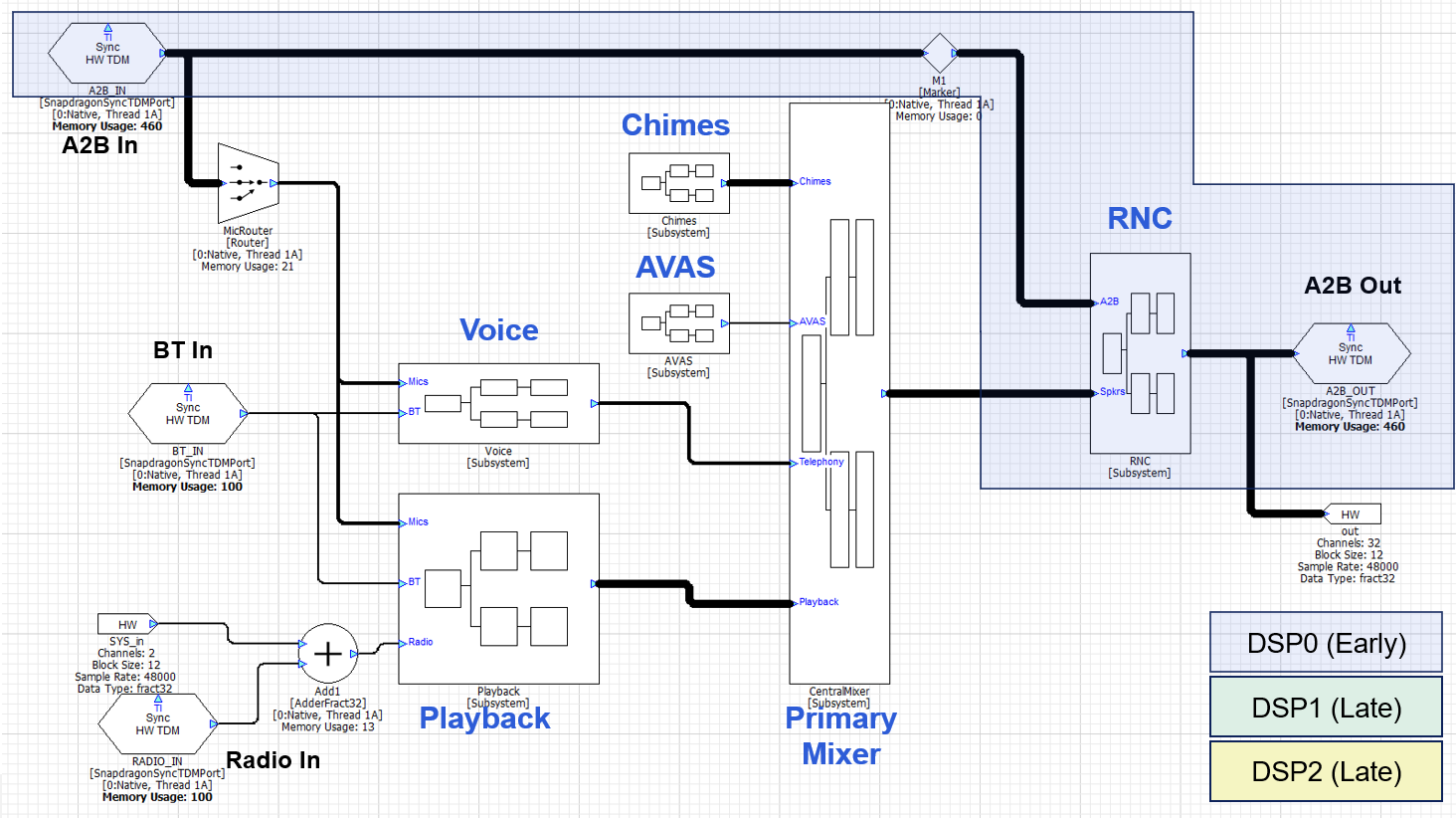
Next lay out the low latency signal path. Which TDM port(s) receives microphones and sensors, and which one(s) drives the loudspeakers? In the design above, we assume that the system uses an A2B network for inputs (sensors and microphones) and outputs (loudspeakers) and that this is the same set of speakers used for early audio. The RNC algorithm will be placed between these TDM ports and in order to minimize latency, the RNC algorithm should also be on DSP0. As mentioned above, we expect that the RNC algorithm will use custom modules, and the algorithm would be late loaded using a Subcanvas. The RNC Subsystem would also have a final mixer that would combine RNC and playback signals. With this design, the low latency signal path is shown below:
TDM Ports, Threads, IPC, and Latency
It is important to understand the input to output latency of your signal flow. This is crucial for latency sensitive algorithms like RNC and telephony, and also important to track for playback algorithms that require time aligned signals. The latency in your signal flow comes from 3 sources: I/O latency, changing threads and cores, and algorithmic latency. A full explanation is provided in the Audio Weaver Architecture Document, and we provide basic information here.
I/O Latency
The Synchronous TDM Port module uses DMA and double buffering. The latency for an input or output port equals 1 block size. Using a TDM port for input and then another TDM port for output adds a total of 2 x block size latency.
Analog Latency
This is the latency through the codecs and audio networks (like A2B or Ethernet) in the system. Refer to the datasheets for your devices to understand the specific latencies.
Changing Threads and Cores
The ChangeThread module sends audio to another thread on the Snapdragon. This thread can be on the same core or on a different core. If the block size does not change, then the latency through the ChangeThread module equals 1 block size.
The ChangeThread module is able to change the block size at the same time as changing the thread or core. In this case, the latency equals the larger of the input or output block size.
Algorithmic Latency
The final latency component is due to the specific modules that are in your signal flow. The vast number of modules in Audio Weaver do not introduce any latency. Examples of zero latency modules are Scalers, Mixers, Routers, Adders, etc. Other modules, like Delays or FIR filters, introduce latency based on their settings.
Audio Weaver can display the accumulated latency from the input pin to a specific point in the signal flow. To enable this, select View → Accumulated Delay in the menu.
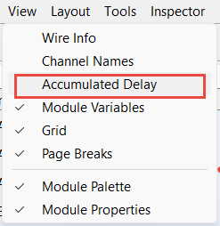
The latency will then be shown and updated whenever you build the system or redraw it. The latency can be shown in either units of samples or milliseconds. This is set on the Global Preferences dialog as shown below:
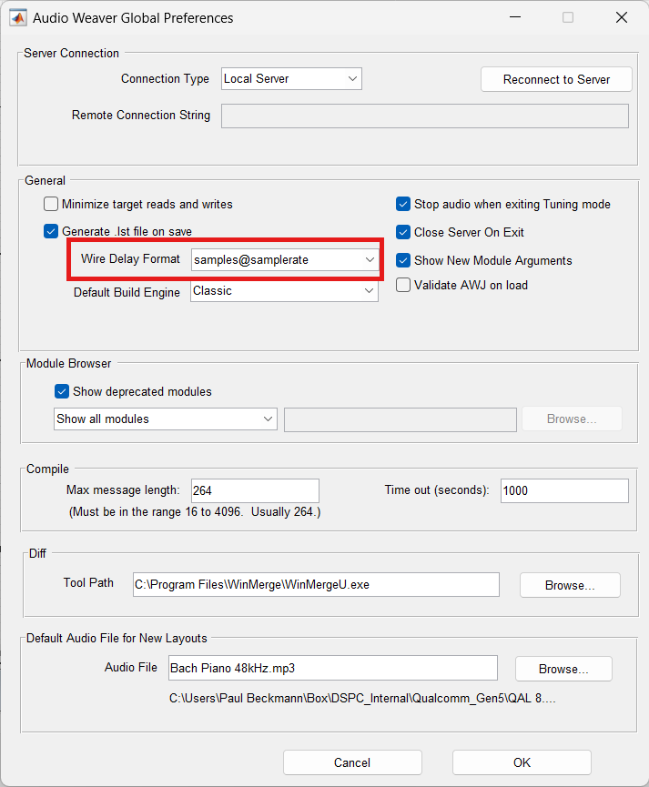
Audio Weaver is able to track the algorithmic latency and the threading latency. The I/O latency and Analog Latency are not included.
Latency Examples
Here are some specific examples to help you understand the principles. A Scaler module will be used to illustrate zero latency modules and a DelayMsec module will be used to illustrate modules which add latency.
Basic I/O
This system operates at a block size of 12 samples at 48 kHz. The only module is a Scaler which introduces no latency. The accumulated latency is shown in samples and is zero at the output TDM port. The I/O latency comes from the BSP code and is not shown in the signal flow. However, it will be 2 x 12 samples = 24 samples. At 48 kHz, the total digital latency is 0.5 msec.
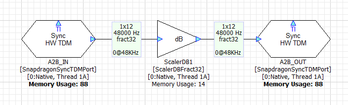
In general, the digital I/O latency through Audio Weaver equals 2 times the block size. On top of this, you need to consider additional latency of A2B and analog I/O. For example, on the SA8255 ADP, the analog latency is 1.1 msec. If you measure the total analog input → analog latencies, you will observe:
| Block Size (samples) | Total latency (msec) |
|---|---|
| 8 | 1.43 |
| 12 | 1.6 |
| 16 | 1.76 |
| 24 | 2.1 |
Algorithmic Latency
Now add a Delay module set to 96 samples. The signal flow now shows:
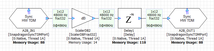
The total digital latency is 96 samples + I/O latency = 120 samples.
Although smaller block sizes achieve lower latencies, they come at the cost of higher CPU load. We recommend using the largest block size possible.
Another restriction in the R4.3 release of Audio Weaver is that all synchronous TDM ports must operate at the same block size and sample rate.
ChangeThread Latency
Changing cores and threads in your signal flow adds additional latency. It doesn't matter if you are switching cores or threads, the latency is always the same and equals 1 block size. If you have a latency sensitive algorithm, then you should keep it on the same core – and same thread – as the TDM ports handling the low latency I/O.
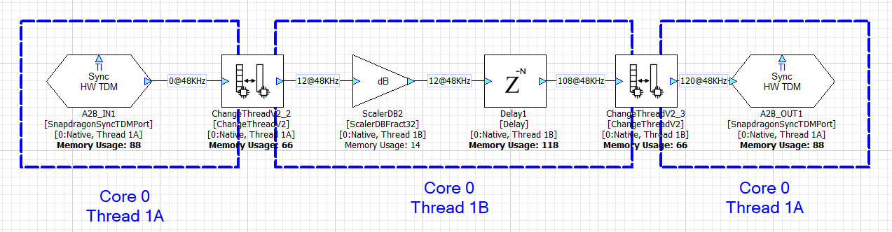
In the first example, we leverage 2 threads on Core 0 to increase the amount of processing power available. The first ChangeThread modules sends audio from thread 1A to thread 1B. The second ChangeThread module sends the data back to thread 1A. Each ChangeThread module adds 12 samples of latency and Audio Weaver shows the total latency as 120 samples (96 samples of delay + 2 x 12 from ChangeThread).
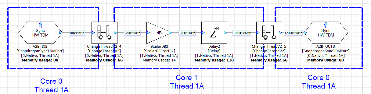
With a slight adjustment, the ChangeThread module can be configured to send data from Core 0 thread 1A to Core 1 thread 1A. This is shown below and the total latency is still 120 samples. Sending data between cores and threads in Audio Weaver adds the same amount of latency.
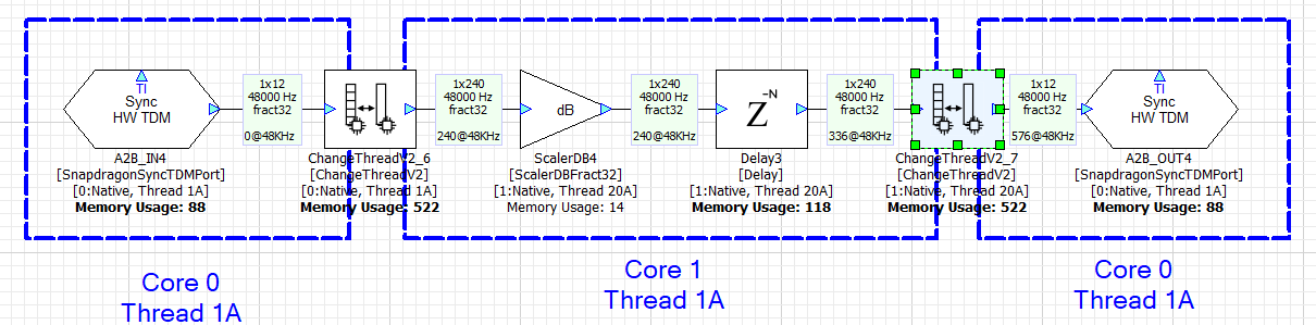
In the next example, we keep Core 0 working at a 12 sample block size and configure Core 1 to use a 240 sample block size. The ChangeThread module handles the buffering up (12 → 240) and the buffering down (240 → 12). Each ChangeThread operation now adds 240 samples of latency and the total latency is 576 samples.
Parameter Control
This section describes the basics of parameter control in AWE-Q. You first need to understand how parameter control works in Audio Weaver and then how this parameter control is exposed in AWE-Q.
Audio Weaver parameter control is based upon a number of core principles:
- The Audio Weaver control APIs are designed to write to directly to module instance variables. You can write to scalar variables or to array variables. Updates are made one variable at a time.
- All variable data types are 32-bits long. Modules can use float, int, uint, and fract32 data types.
- Modules are identified on the target based on their objectID. Each module has a unique objectID which is set in Designer.
- Variables within a module are identified based on their offset from the start of the module instance structure. The combination of objectID and variable offset uniquely identifies where in memory a variable is located.
- Using the Generate Target Files feature in Designer, you can generate a Container file which contains the objectIDs and offsets of all tunable module variables. For each tunable variable, Designer additionally generates a HANDLE which encodes the objectID, offset, coreID, and whether the variable is a scalar or an array.
- The Container file also contains information about the data type and range of each variable.
- The Container also contains the length of arrays and the Audio Weaver APIs throw an error if you read or write outside of array bounds.
- Audio Weaver does not distinguish between controlling modules during a tuning session (when connected to the Designer PC tools) and controlling modules at run-time in the final deployed system. Similar concepts and APIs are used in both cases.
Assigning objectIDs
You assign objectIDs in Designer by right-clicking on a module and selecting ObjectIDs → Assign. Alternatively, you can enter an objectID in the module's Property View.
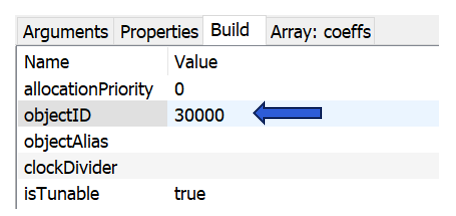
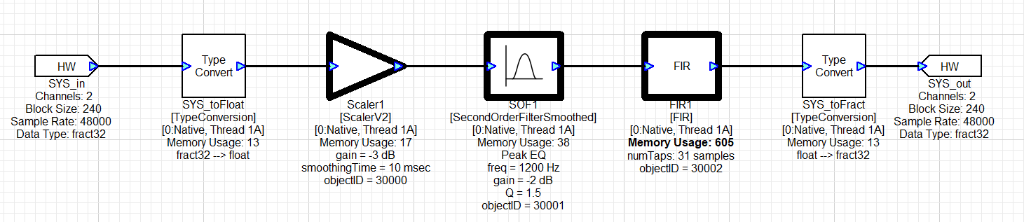
By default, the field "objectID" is empty and the objectID will be automatically assigned when the system is built. (Wires, modules, and layouts are all assigned objectIDs at build time. They are sequentially numbered starting at 1.) If you want to control the module at run-time, then you must assign a custom objectID. Custom objectIDs are in the range 30000 to 32767.
Modules that have custom objectID assigned are drawn in bold in Designer.
Generating Target Files
After you have assigned objectIDs in your system, you generate the Container file which is used by AWE Target Configurator utility. Go to the Tools → Generate Target Files menu item in Designer. It will open the dialog shown below. Use the "Container Setting" panel on the right-hand side and generate a "Toplevel" container.
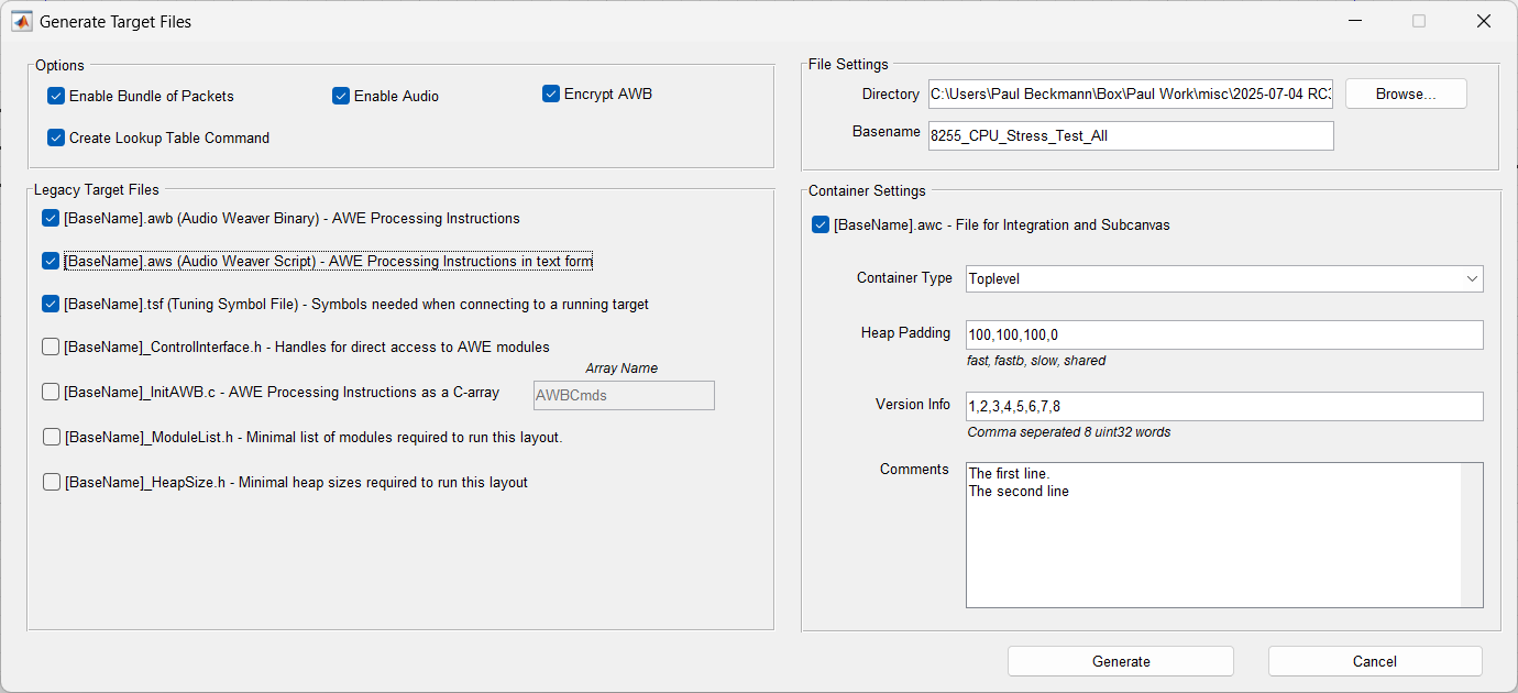
The Container file has an AWC extension and internally uses a JSON format. The AWC file contains:
- Version information / Comments / Build date and time
- Heap sizes used by your design
- Details on the layouts (threads) used
- Input and output device details
- A list of module classes used
- Information on all tunable modules and variables
- Binary AWB contents. This can optionally be encrypted
The AWC file is used as input to the AWE Target Configurator. AWETC generates a binary file which is used on the target and includes all tuning information.
Best Practices Using Control Arrays
A typical automotive system has 20 to 30 modules which need to be controlled at run-time. One possible approach to designing the control interface is to assign objectIDs to each of these modules and generating the container file as discussed above. This is a fine approach, but the main downside is that every time you change your control API, you'll need to generate the container and rebuild the Audio Manager on the HLOS.
An alternate approach is to aggregate all controllable parameters into a single SourceInt module. This module holds an array of N values and has an objectID assigned to it. Then, individual values are extracted from this array and written into specific module variables using the MapperControl and ParamSet modules. The advantage of this approach is that you would have to expose only a single objectID and can make changes to the control code via changes to the Audio Weaver signal flow. Plus, if your design has 40 tunable variables, oversize the control array to 50 values. This gives you expansion in the future. This is the recommended approach when controlling large signal flows, like automotive systems.
An example of using a control array is shown in the figure below. This shows a portion of the top-level system and you'll notice that there is a SourceInt module called "Control_IPC_In" to which the HLOS writes and a SinkInt module called "Control-IPC_Out" that can be read by the HLOS.
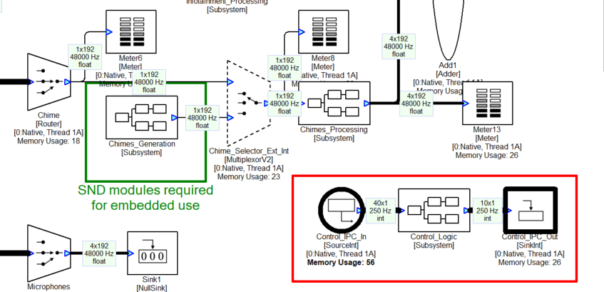 Figure: Portion of an automotive signal flow which shows consolidated control via SourceInt and SinkInt modules.
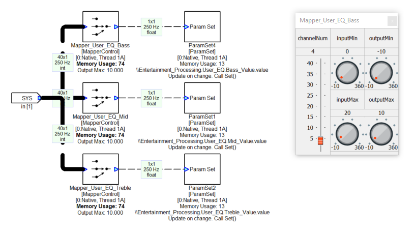
Inside the Control_Logic subsystem are multiple ParamSet modules which write into various modules. For example, the control array has 3 values for controlling the Bass, Mid, and Treble tone controls. The MapperControl module extracts one of the 3 values (channelNum as shown on the inspector), clips input values to the range [0 20], and then remaps linearly to the dB range of [-10 +10]. This is then fed into a ParamSet module which writes the value into another module.
Audio System Startup
System flashing — TBD. This section is still under development.